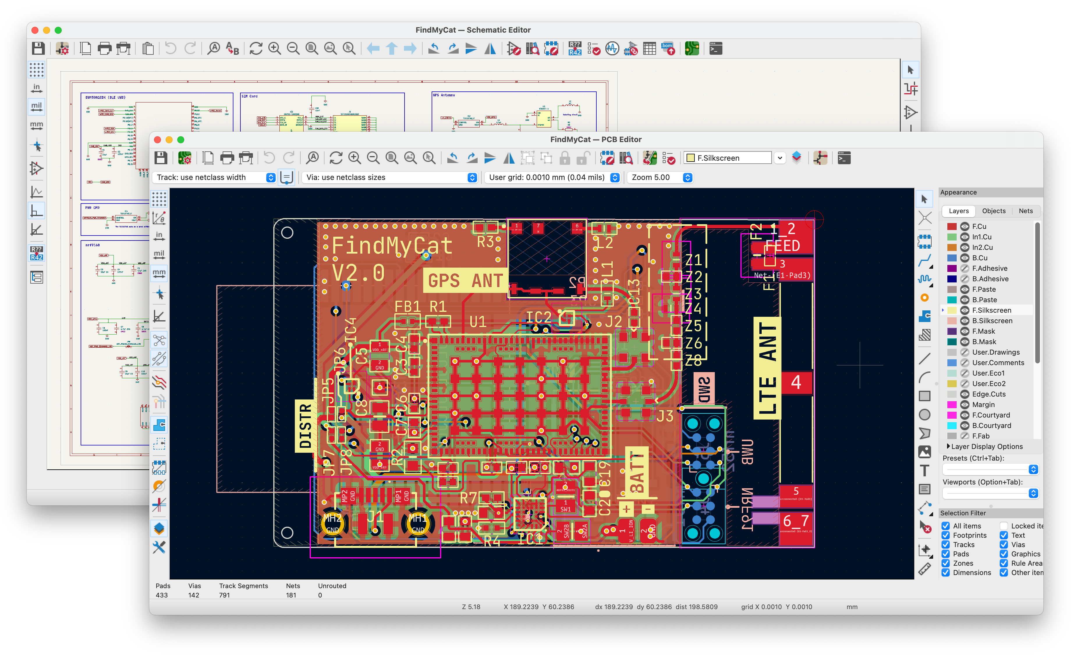
FindMyCat PCB
The PCB is the heart of FindMyCat. It is a 4 layer board with a couple BGAs and Impedance controlled traces for Antennas with components placed on both sides of the PCB.
Manufacturing notes
Following are important considerations when manufacturing the PCB.
- LTE and GPS Traces must be impedance controlled at 50Ω impedance.
- All VIAs must be filled and capped. (VIA in Pad)
- Prefer the
ENIGsurface finish since BGA components are involved.
Downloads
These are the files you should need to manufacture the PCB. The Gerber files also have the drill files zipped.
Gerber Files
FindMyCat-Gerber.zip
PCB Schematic
FindMyCat-Schematic.pdf
Upcoming Improvements
Following are the improvements I want to make when doing a PCB design revision.
-
Avoiding BGAs when possible: While BGA components provide a compact design, they substantially increase manufacturing expenses. For instance, in order to produce a PCB compatible with BGAs, the manufacturer must accommodate VIA in pad, ENIG surface finish, and X-Ray inspection for post-assembly. These requirements collectively contribute to a considerable cost. I think there is enough space on the FindMyCat PCB currently that some BGA components could be swapped for more easily manufacturable alternative SMD package.
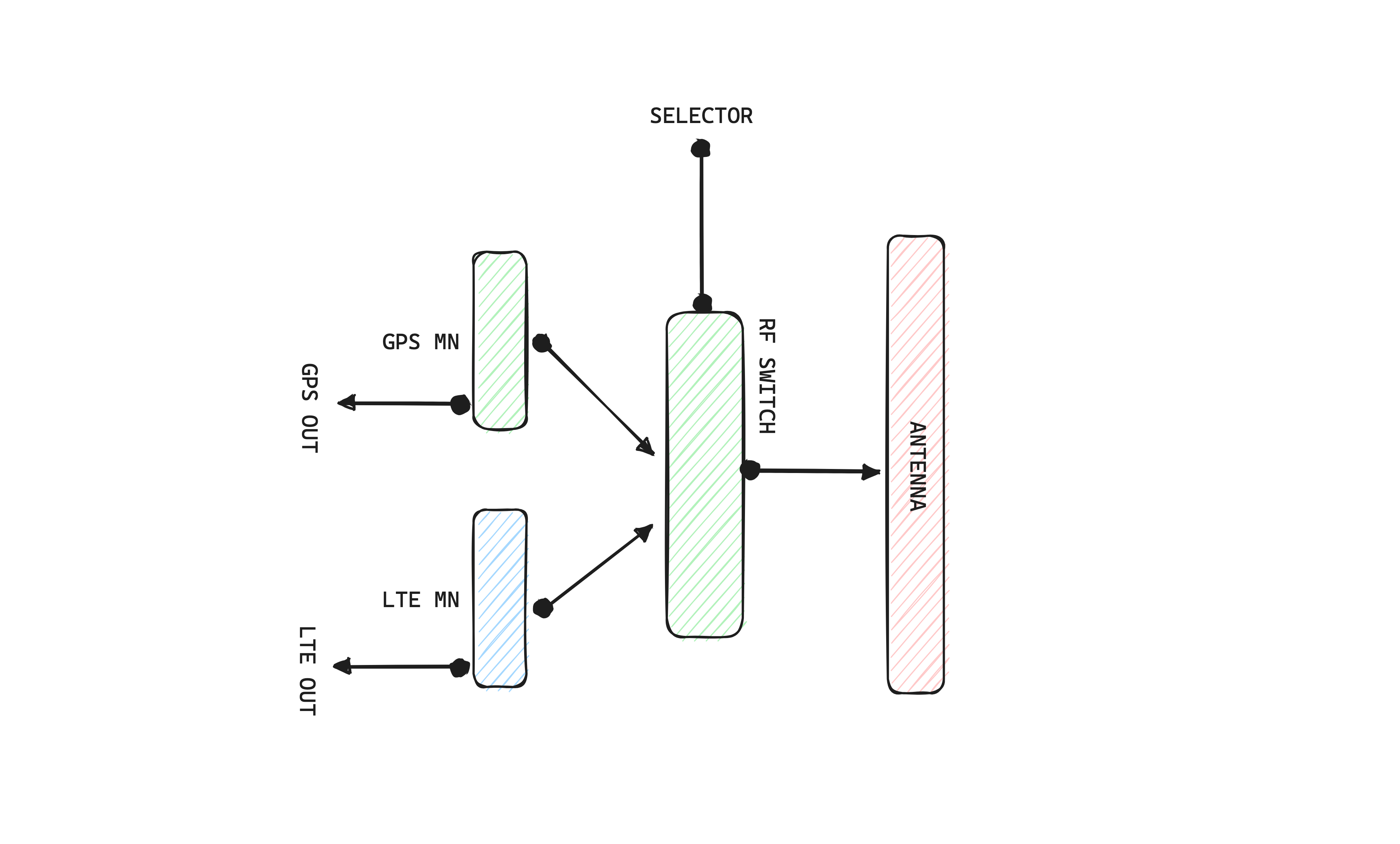
-
Consolidating Antennas: Since the NRF-9160 only uses LTE or GPS radio at one time, the two antennas could be consolidated into one. Something like the following, an RF switch that has two different Matching networks, one for GPS and another for LTE. With a selector signal, the RF Switch could connect either one of them to the RF inputs of NRF-9160.